
I am getting ready to refit my case and completely redo the wiring inside. I will be reinstalling the LEDs and installing new ones as well as simplifying the number of connections and wires inside of my case. Preliminary designs and thoughts are here: http://imgur.com/a/WZBSi .
I pretty much now have an idea of what I want to do, now I'm having to go over implementation.
*UPDATE 10-25-16*
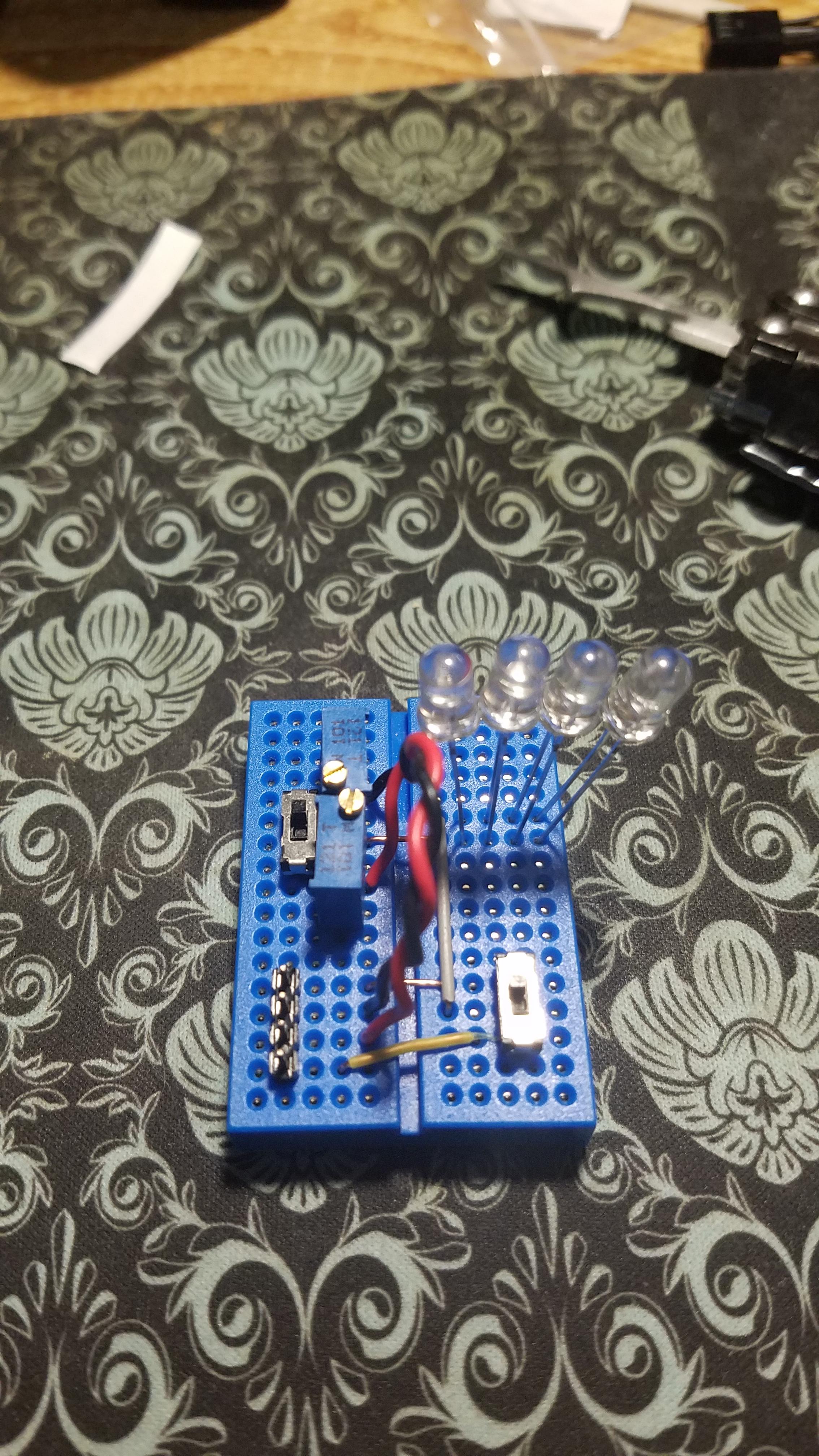
This is the test design for the switching circuit. The user can select between 12 volts and 5 volts to power the circuit. A second switch will allow the user to pick the appropriate pre-set resistance for each voltage. It looks like anything less than a series circuit could cause the 12v pot to fail.
*Update 10-26-16*
[video=youtube]http://www.youtube.com/watch?v=TFcViy1Kj7A[/video]
http://youtu.be/TFcViy1Kj7A
*Update 10-27-16*
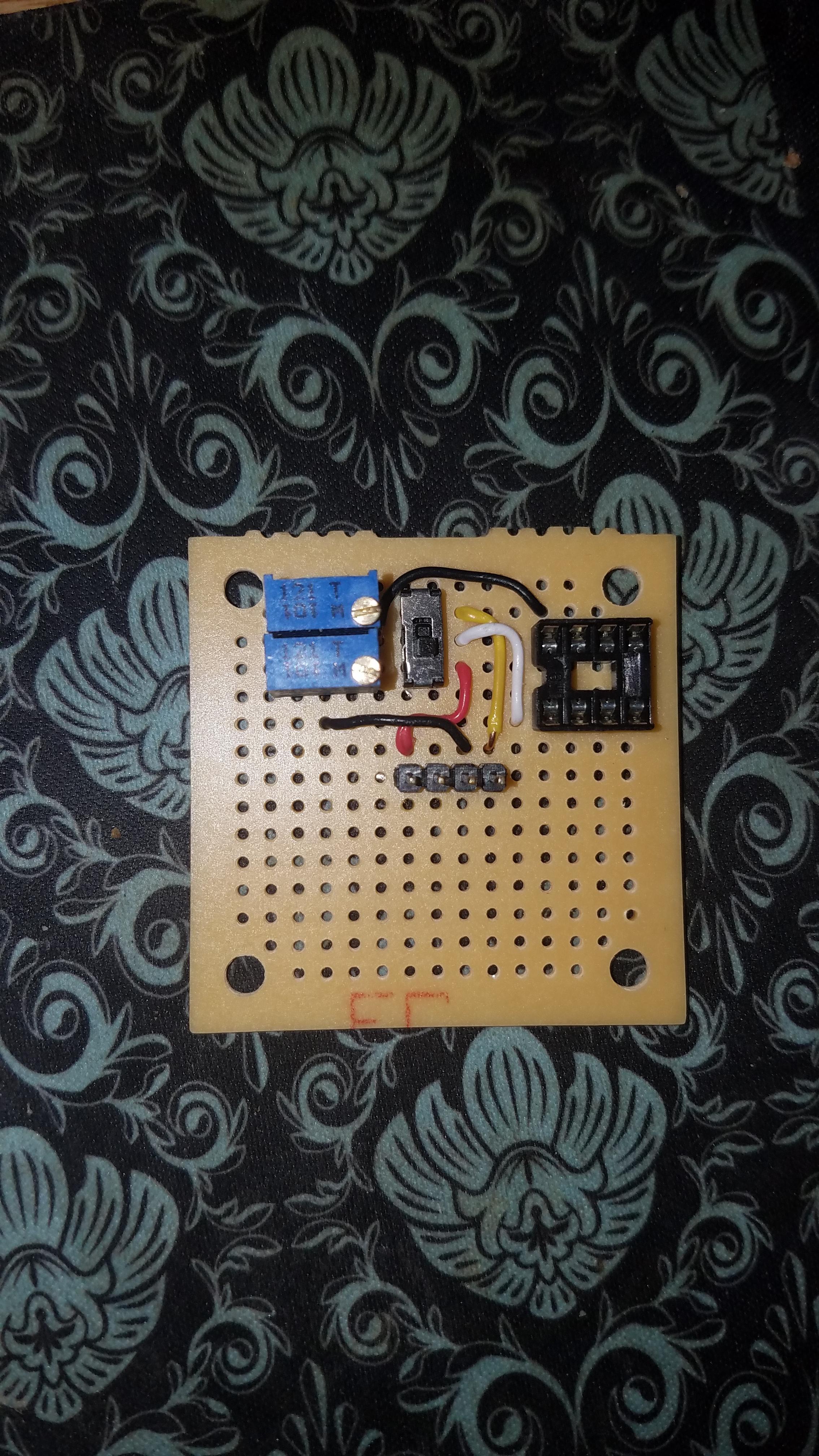
Skipped pictures of an iteration. Eliminated a switch in this iteration. Circuit selection is done by a single DPDT switch. Selecting the voltage will select the appropriate configurable resistance. The IC socket will serve as a connection point for testing LEDs and will likely not be included in the final version.
*UPDATE 11/22/2016*
[video=youtube]www.youtube.com/watch?v=1iygO8jO42g[/video]
http://youtu.be/1iygO8jO42g
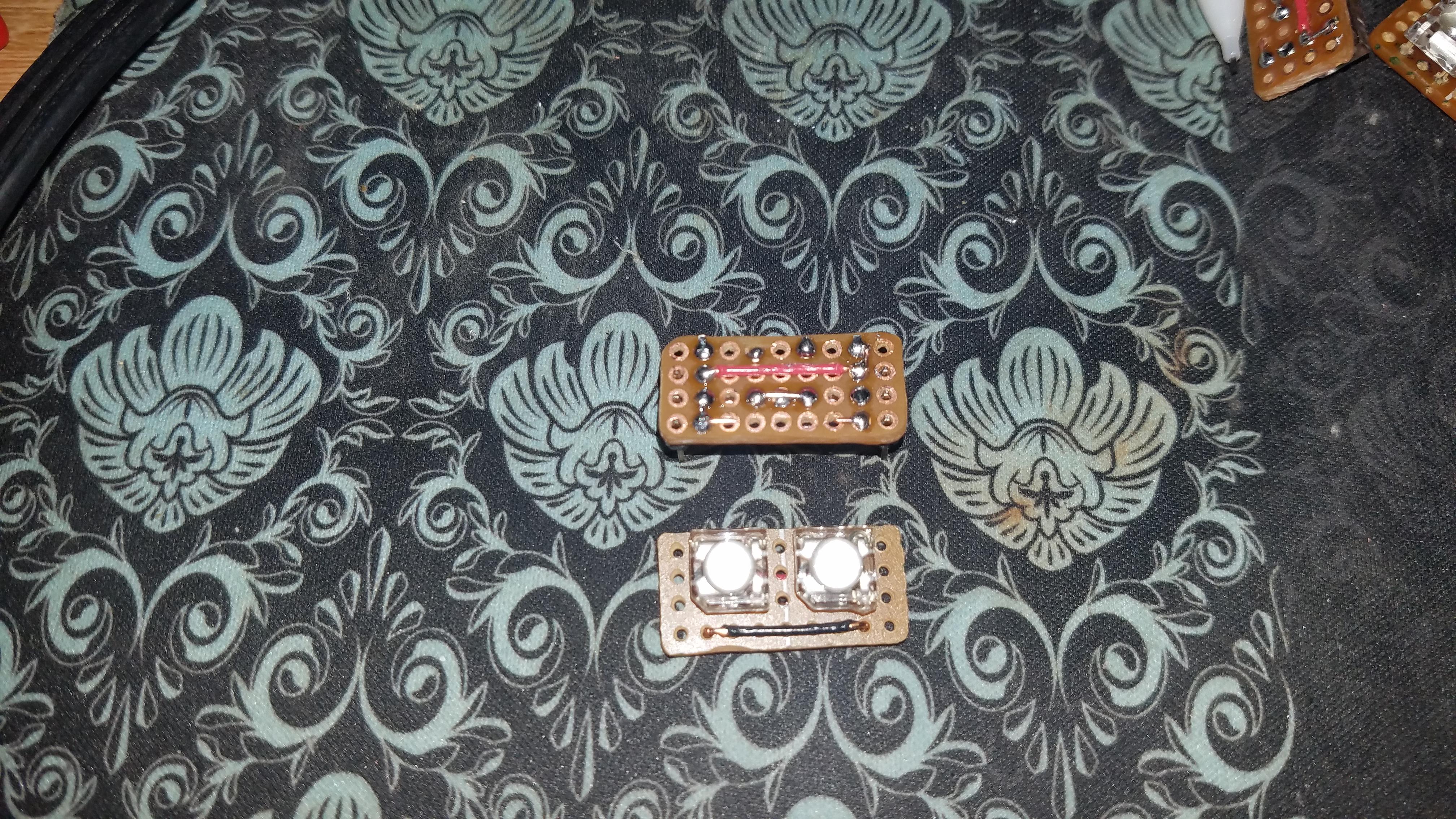
Here I have a working low-pass filter hooked up to a bank of UV LEDs. These will go to the reactive window on my case. I have since built a set of modules that hold two LEDs each. These can be chained together without modifying the voltages needed for the chain to work.
I pretty much now have an idea of what I want to do, now I'm having to go over implementation.
*UPDATE 10-25-16*
This is the test design for the switching circuit. The user can select between 12 volts and 5 volts to power the circuit. A second switch will allow the user to pick the appropriate pre-set resistance for each voltage. It looks like anything less than a series circuit could cause the 12v pot to fail.
*Update 10-26-16*
[video=youtube]http://www.youtube.com/watch?v=TFcViy1Kj7A[/video]
http://youtu.be/TFcViy1Kj7A
*Update 10-27-16*
Skipped pictures of an iteration. Eliminated a switch in this iteration. Circuit selection is done by a single DPDT switch. Selecting the voltage will select the appropriate configurable resistance. The IC socket will serve as a connection point for testing LEDs and will likely not be included in the final version.
*UPDATE 11/22/2016*
[video=youtube]www.youtube.com/watch?v=1iygO8jO42g[/video]
http://youtu.be/1iygO8jO42g
Here I have a working low-pass filter hooked up to a bank of UV LEDs. These will go to the reactive window on my case. I have since built a set of modules that hold two LEDs each. These can be chained together without modifying the voltages needed for the chain to work.